Mach Command, the standard Mach 1 software
Mach Command is CN-Seamless' proprietary software for operating the Mach 1. We recommend keeping your machine on the latest build. To be notified of each release, sign up on the Software page. To run Mach Command from a device other than the included tablet, see the manual for connecting external devices.
Tip: in the figures, tap any numbered callout badge to jump to what it means.
Overview.
New to controlling automated products? Don't worry. Mach Command was designed to follow the workflow fabricators already use. Imagine replacing a cracked bucket ear with a hand torch. Here's what you'd do, and where each step lives in Mach Command:
- Design: carve a piece of cardboard into a template matching the profile of the part.
- Place: set the cardboard on a fresh piece of plate and trace it with soapstone.
- Materials: set your regulators to the right pressure and plan how you'll pierce and how fast you'll move for a clean cut.
- Run: cut your design where you placed it, adapting on the fly. Since Mach Command is software, you run the program.
As you build, you move left to right across the four core screens: Design → Place → Materials → Run.
Core screens & layout.
The Action Sidebar is always on the right-hand side, the machine's physical controls:
- Emergency Reset a6: the red hand halts power to the arms and raises them to the maximum height.
- Lock / Unlock a7: move the arms freely when unlocked, and freeze them when locked. Especially useful when the Mach 1 is mounted vertically.
- O2 or Plasma Test a8: turns on the cutting oxygen or the plasma arc, depending on whether the oxy-fuel or plasma module is installed.
- Up & Down arrows a9: touch and hold to raise or lower the arms manually.
In the top right, there's a Mini Menu a10 which contains the following:
-Units b1 for toggling between the English and Metric System.
-Home b2 for reseting the background to the default view.
-Settings b3 for troubleshooting and system preferences.
-Undo & Redo b4 for any action in the Design screen.
-Reset Place b5 to start fresh in the Place screen.


Design.
There are often several ways to reach the same goal in Mach Command. First-timers should focus on the Basic features and master the Classic Design space before moving to Point 2 Point (P2P). If you don't see the Classic background, tap the Classic / P2P Toggle c1. Classic's background has a red X-axis c2 and a green Y-axis c3; where they intersect is the Design Origin c4.

Basic actions
- Navigation: pinch two fingers on the background to zoom in or out. Drag one finger on the background to pan around the screen.
Add Shape d1: scroll through the dozens of pre-loaded templates and tap one to bring the shape to the Classic Design.

Edit Shapes: Tap directly on the outline e1 of any shape to edit it.
- Tapping on the inside of the shape will not open the edit menu, so if you can't tap into the shape, pinch to zoom in and tap the outline of it.
- The shape you're actively editing will turn blue.
Shape Attributes: The edit menu lets you modify variables specific to the selected shape. While the exact attributes vary from shape to shape, these are generally the types of attributes and their meaning:
- Side e2: for closed shapes, this corresponds to the side of shape which is meant to be pierced. For example, a hole would be inside while gusset would be an outside pierce. Inside shapes will be shown as shaded in for easy visual identification.
- Locating Position e3: the critical point on the shape which you are dimensioning positions from.
- X/Y Position e4: the distance between the Locating Position and the Origin in both X (horizontal) and Y (vertical) directions. This may also be modified by touching and dragging along an outline of a shape.
- Size e5: either a length, width, height, diameter dimension.
- Rotation e6: in degrees between the X-axis and default orientation.
Other Edit Options

Editing Attributes using one of the following options.
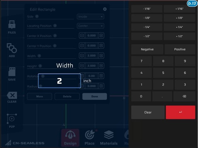
- tap directly on the value e10 of an attribute to bring up a keyboard allowing you to type an exact value.
- use the fraction buttons f1 for quick calculations.
- use +/− on either side of the value to nudge it in pre-determined increments without opening the keyboard.
Tip: when starting out, move all shapes into one quadrant to make the Place Screen much simpler.
- Save g1 : give the design a name and either tap "Save" to save your design to the machine directly, or "Save to Flash Drive" to save it directly to the flash drive plugged into the back of the machine.
- Clear g2 : will wipe the entire design to give you a clean slate. This can be undone b4 if clicked accidentally.

Loading Designs
Clicking Files h1 allows you to load previously saved designs either directly from the machine h2 or from the flash drive h3 plugged into the machine.
- Navigate the folders to find the design you'd like to load
- Select the file you'd like to load (must be a .DXF to load from flash drive)
- Modify the scale h4 if you'd like to load the .DXF larger or smaller than it was exported.
- Select the appropriate units h5 if the .DXF file was saved without specific units.
- If the DXF file was exported far away from the sketch origin, click Center DXF h6 so it will load in view on Classic Design screen.

Groups
When a DXF is loaded, all shapes and profiles within it are treated as one group. The purpose of a group is to maintain the relationships and dimensions of multiple shapes with respect to one another within their group. If you make a base plate, for example, you would want the bolt hole pattern and the outer rectangle to move with each other once you have them designed.
Tapping on the outline of any element in a group allows you to edit the entire group, including the position, rotation, and more.
- All shapes within a group will become highlighted.
- Tapping again on an shape within a group will allow you to edit that specific shape.
 1
1 Creating a New Group Touch and hold anywhere j1 in space to bring up the Group Shapes option. Select all of the elements you'd like to be grouped together, including other groups, and then select create group.

Combine
Similar to grouping shapes, touch and hold anywhere in space to bring up the Combine menu. Here, you can select any two overlapping shapes and combine them in the desired manner to achieve even more complex designs.

Advanced Edit and Nesting
Selecting More e7 on any individual shape or group will expand a menu of advanced options, most useful for nesting multiple parts in a single design.
- Pattern l1 allows you to generate an array of the selected shape or group either with rectangular or circular spacing. Elements in a pattern all maintain their relationship to the originally patterned shape, which can still be edited after generating the pattern.
- Clone l2 makes an exact copy of the shape or group which becomes unlinked to the original parent of the clone.
- Mirror X/Y l3 mirrors the selected shape or group across the X or Y axis.

Nesting
The most effective way to nest elements, is to generate a group of items to be nested in the shape of rectangular building blocks, then create a rectangular pattern of that group.
In the example of an oddly shaped design like a triangle. The most efficient thing to do is clone the element, mirror it, and position it into a building block you can group and pattern.

Point to Point: swap to the P2P and Classic Design spaces with Classic / P2P Toggle c1.
- In P2P, your background will change to show a real-time render of the Mach 1 from the overhead perspective.
- You'll notice the attachment you have installed will show up on the machine. n1
- As the arms of the machine are moved, the arms on the screen will move with it. Remember to unlock the arms to move them. a7
- The space n2 between the grey boundary on the machine and the circle surrounding the machine represents the usable cutting area. It is recommended to cut to the left, front, or right of the machine when possible to avoid the cables or hoses attached to the rear of the machine.

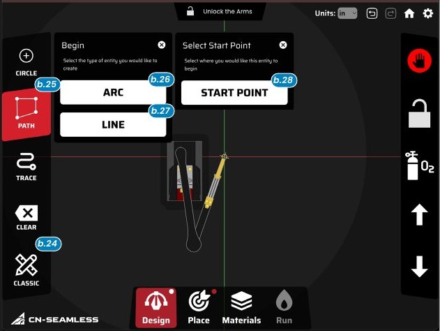
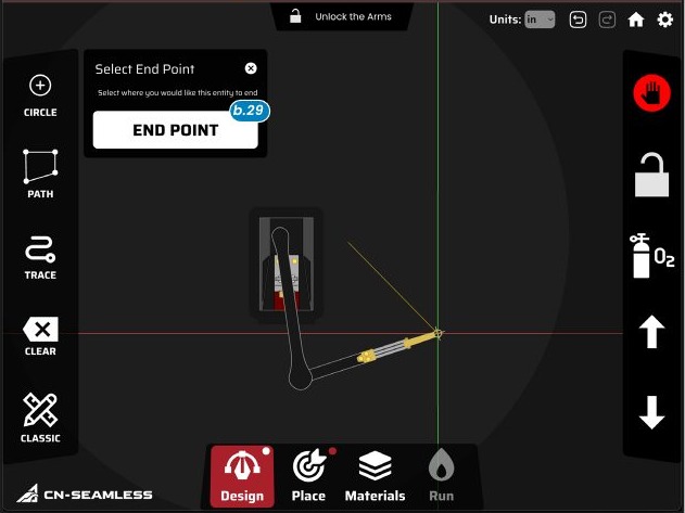
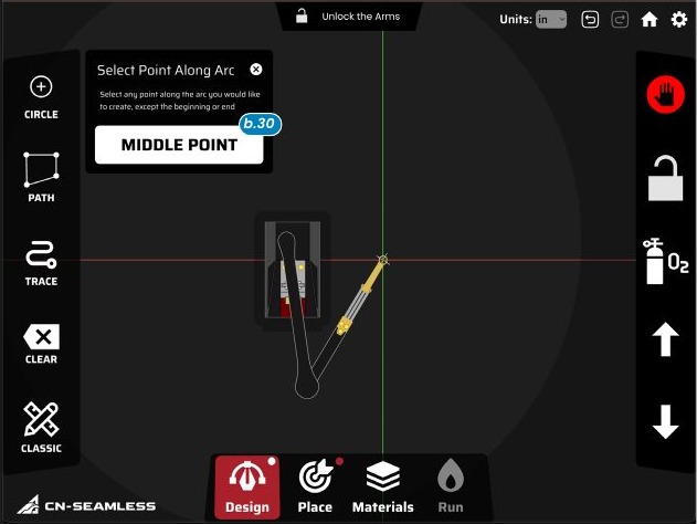
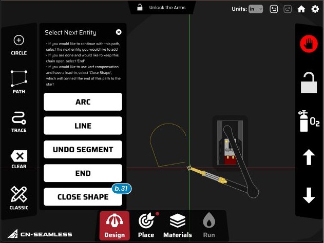
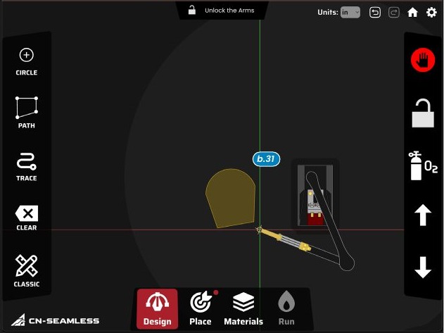
- Circle t1 drops a circle at the tool.
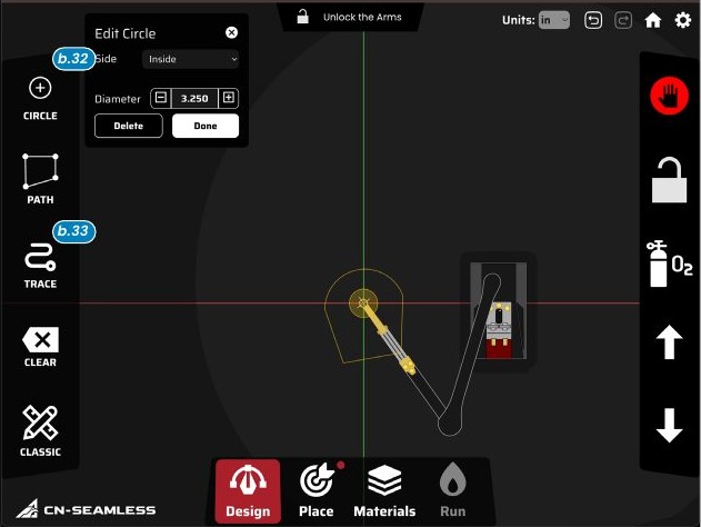
- Trace t2 follows the tool's motion for complex profiles off a physical template, though Path is usually more precise.
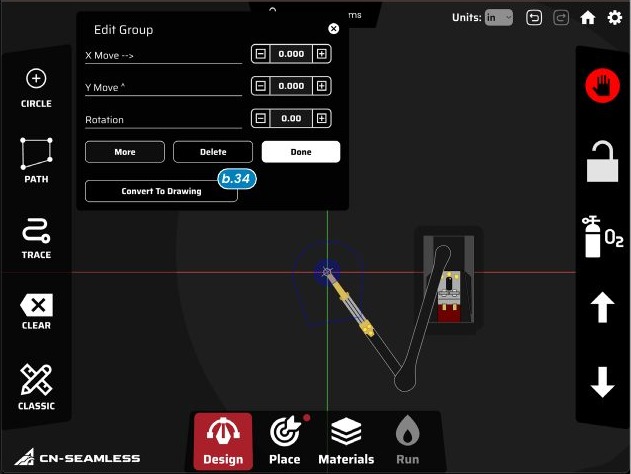
- Convert to Drawing u1: P2P designs aren't relocated in Place. To cut them somewhere else, group them and "Convert to Drawing" to move them into Classic Design, where they edit like any shape. (If P2P parts should be cut exactly where they were traced, you can skip Place entirely.)
Place.
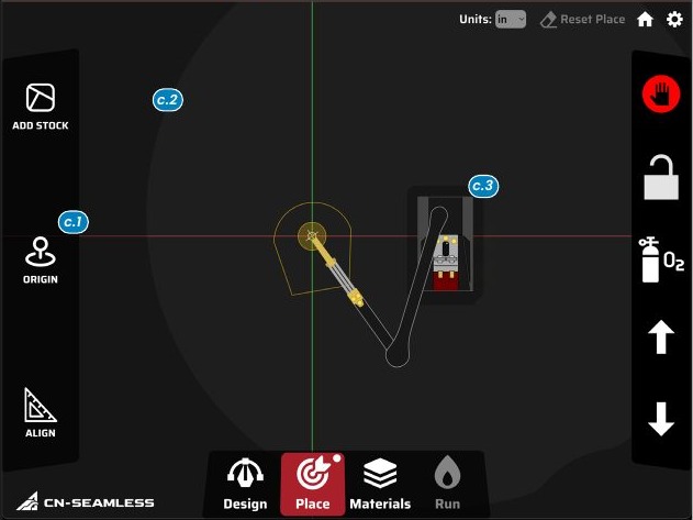
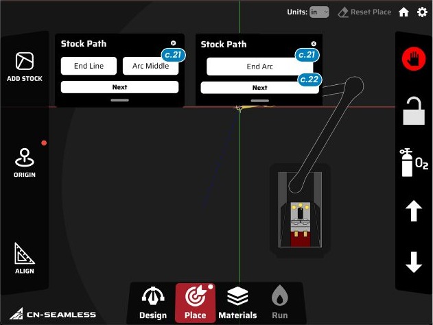
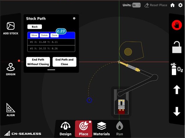
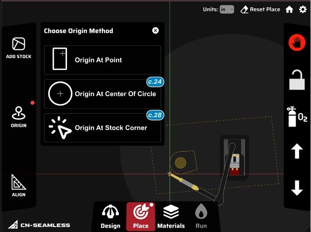
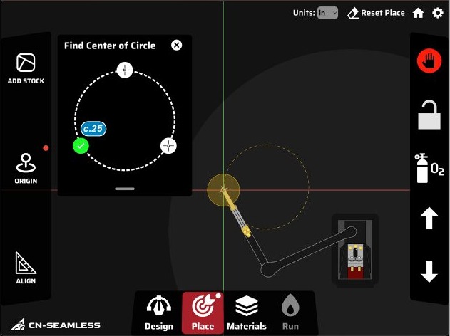
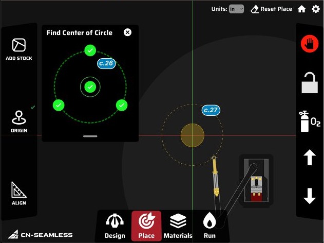
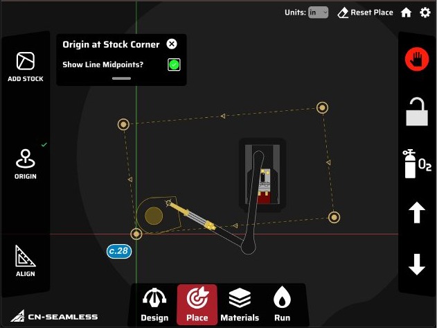
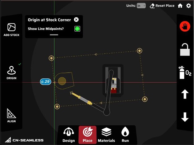
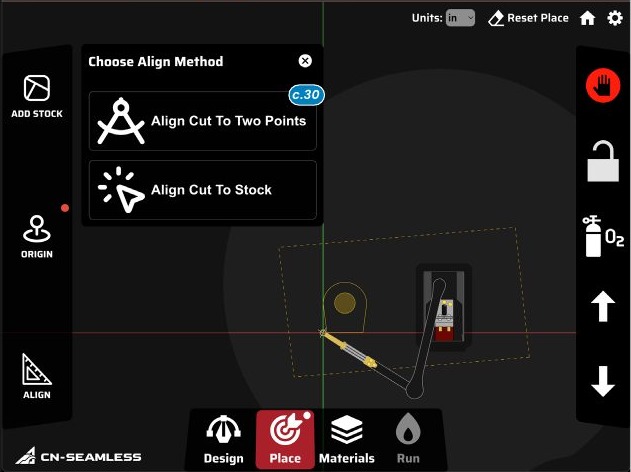
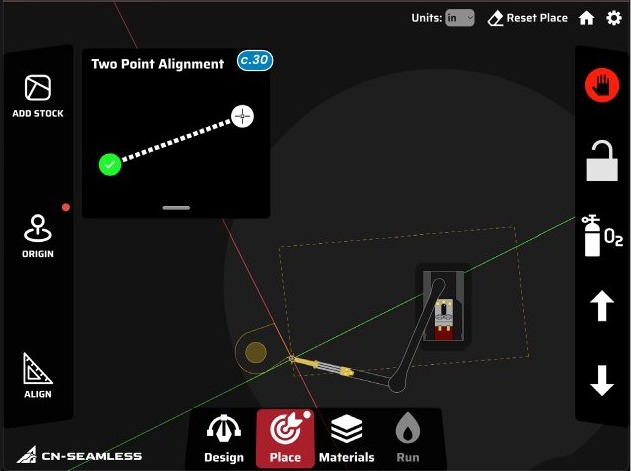
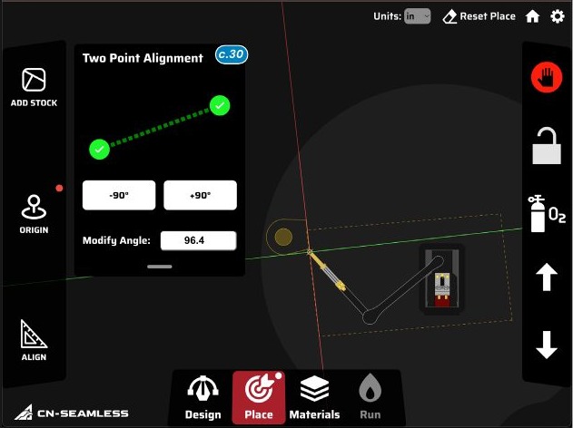
Having your part in Classic Design is like having the cardboard copy. Now you need to place it on your steel to mark where to cut. Until you use Place, the Mach 1 doesn't know where to cut. The background shows a render of the Mach 1 and a crosshair at the center of the tool; until an Origin v1 is set, the Design Origin moves with the arm. You'll also see the reach circle v2, where the machine can safely reach, and a base boundary v3 where cutting is restricted so the machine can't hit itself. Pinch and rotate until the on-screen model matches how the machine sits in front of you.
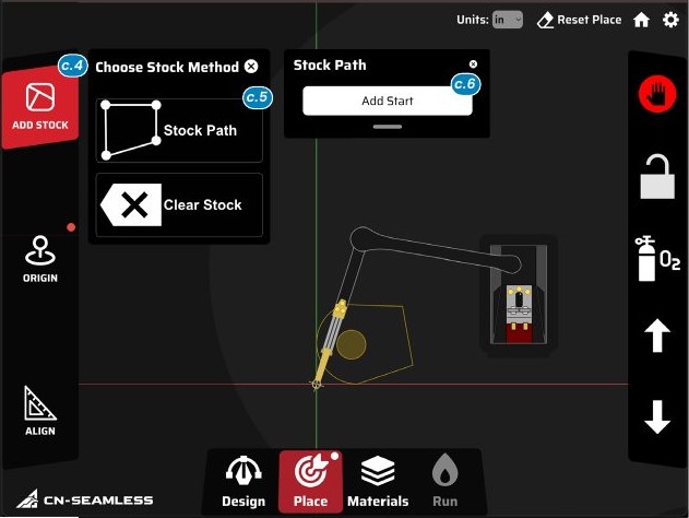
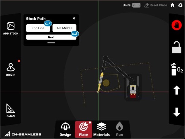
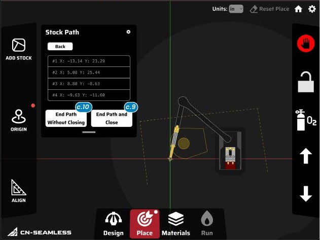
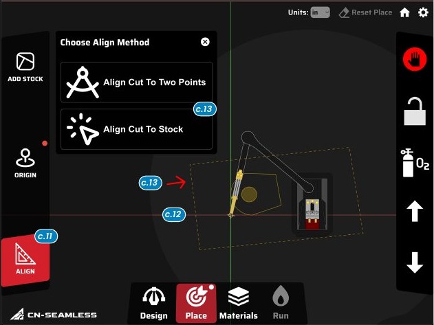
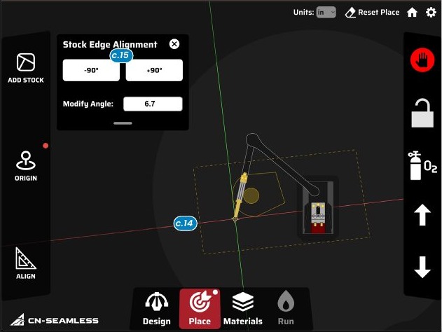
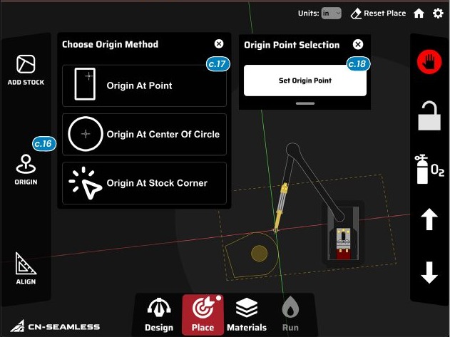
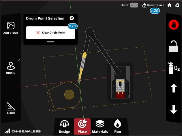
If the shapes don't move with the tool on this screen, they were designed in P2P and need to be converted to Classic Design u1.
Advanced Place
Materials.
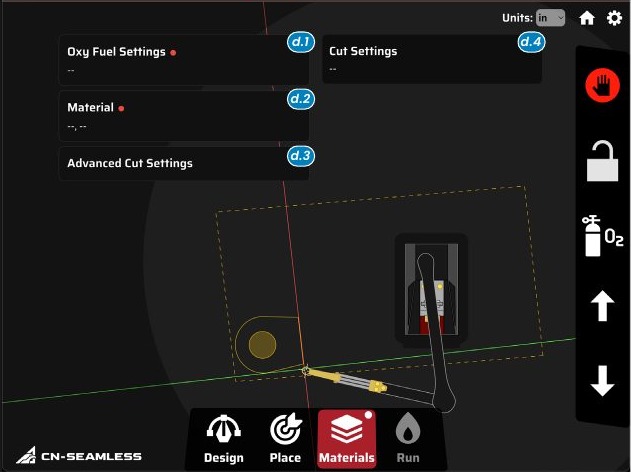
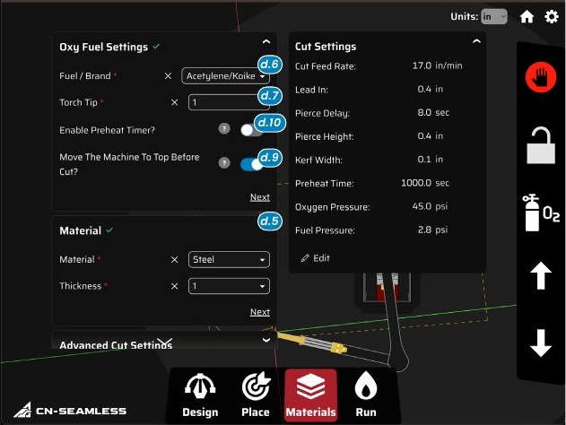
Basic oxy-fuel
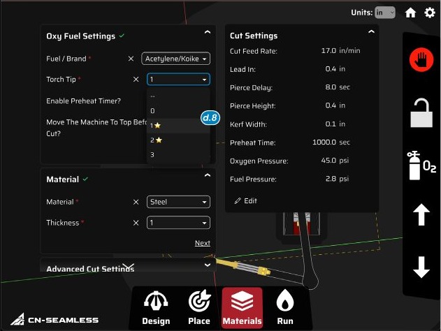
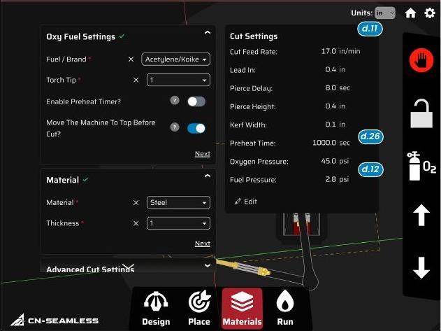
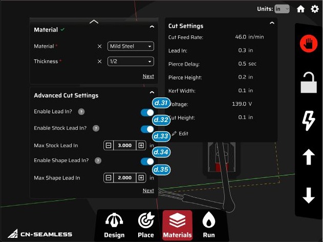
Select your Material ao1 (usually mild steel) and its thickness first. Set Oxy-Fuel Settings ao2: fuel and tip brand (Koike for most; legacy Harris torches select Harris). Tap Torch Tip ao3 and Mach Command stars the recommended tip for that thickness ap1. Turn on "Move the Machine to Top Before Cut" ao4 and turn off the preheat timer ao5. Use the default Cut Settings aq1 to start. Recommended regulator pressures are shown at the bottom aq2.
Basic plasma
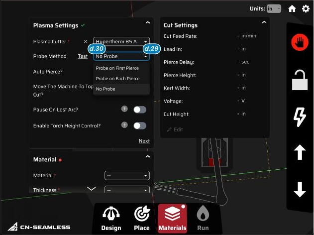
In Plasma Settings ar1, select your cutter, set Probe Method to "No Probe" ar2, turn off Auto Pierce ar3, turn on "Move Machine to Top Before Cut" ar4, turn off "Pause on Lost Arc" ar5, and turn off Torch Height Control ar6. Set Material ar7 and thickness, then use the default Cut Settings ar8. You can also edit the Materials panel while the machine is running.
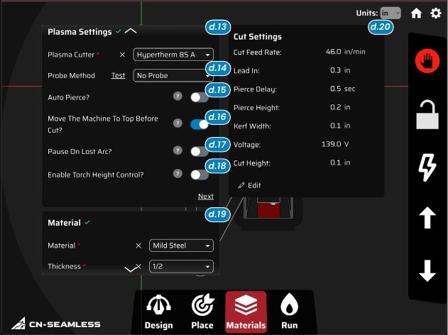
Cut settings explained
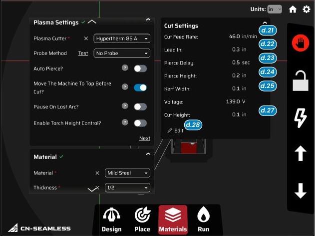
Advanced plasma
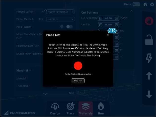
- Probe at1: the torch touches off the material to register the perfect cut height ("probe on first pierce" reuses that value; "probe on every pierce" re-probes each time). Use the Probe Test at2 au1 to confirm continuity. A flashing green means good contact. Probing works best on clean material with the machine mounted directly to it.
Run.
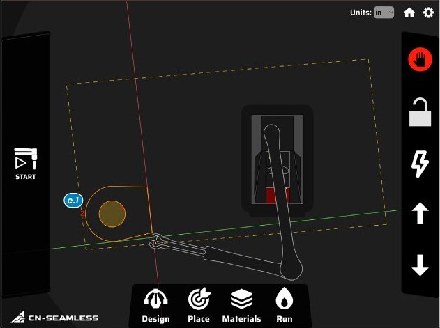
When you enter Run, Mach Command generates the lead-ins and a motion plan aw1: each shape gets a numbered pierce point showing the order it'll be cut.
Starting the cut
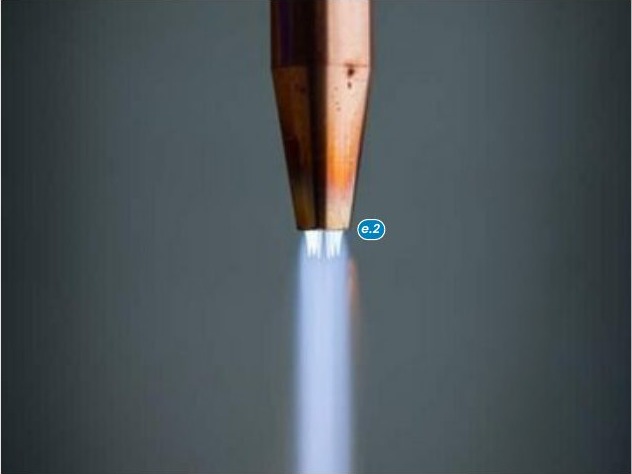
- Oxy-fuel: move the torch off the material and light it with the red fuel valve to a neutral flame, then add oxygen with the blue valve until you get sharp blue cones ax1.
- The O2 button ay1 verifies the cutting jet.
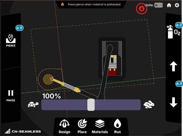
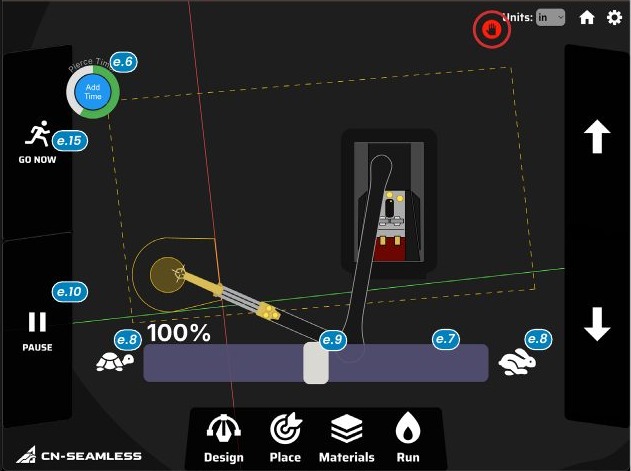
- Plasma: Start locks the arm and moves to the first pierce. If "no probe" is selected, lower to the correct height; if probing is on, make sure it triggers on contact. Press Pierce to start: the arc turns on, holds for the pierce delay az1, then moves along the path at the feed rate.
Monitoring the cut
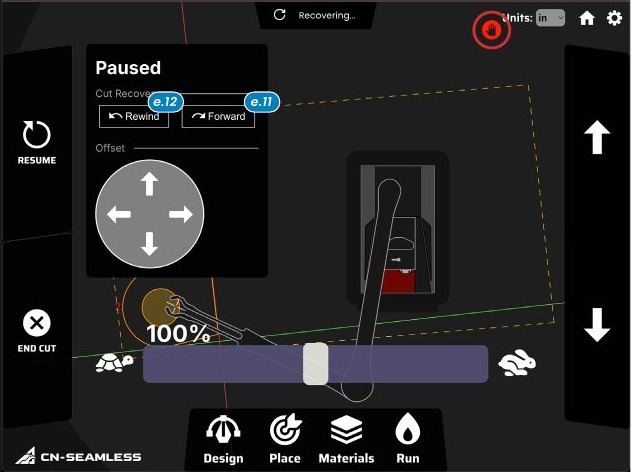
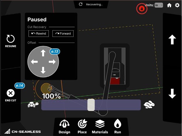
- Cut height ay2: the up/down arrows raise or lower the torch during the cut.
Troubleshooting.
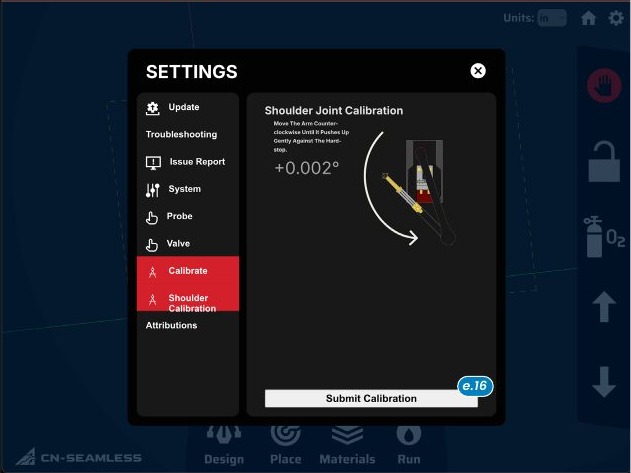
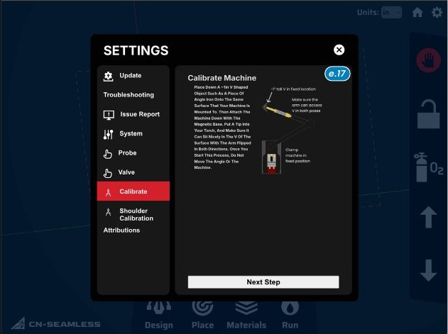
If the physical arms don't match what's shown on screen, you may need to calibrate. In Settings b4, check Shoulder Calibration first: rotate the base arm counter-clockwise to the hard stop, then "Submit Calibration" bc1. It should read around zero degrees when the shoulder is calibrated. Then follow the Calibrate screen to set the angle between the first and second arm bd1.